A Rover Antenna for the 2016 INQP
After operating mobile in the INQP for 2013, 2014 and 2015
(which included winning the mobile category in 2014) I thought a
change was in order to keep the experience fresh. My operating
partner, Andy K9ELF, agreed.
Our 2015 effort included over 500 miles of driving through 21
different counties and, as is typical of any mobile, operating from a
moving vehicle with compromise antennas. Let me tell you, we were
tired puppies at the end of that day. We settled on a Rover operation
for 2016, which would still allow us to activate multiple counties but use
a “real” antenna and with considerably less driving.
Of course, that begs the question of what antenna to use. Some
rovers will stage simple antennas, typically dipoles, in different
locations in the days before the contest, and all they have to do during
the contest is drive to a new spot, plug in, and start calling CQ. That’s
a great strategy but it does entail a fair amount of work to build (or buy)
all those antennas, get permission of the various property owners to
erect them, put the antennas up, and then take them down after the
contest. We thought that an antenna we could carry with us that could
be quickly deployed at each location and then stowed when it was time
to move on made more sense.
To make a long story short, we settled on a 40 and 20 meter
folded skeleton sleeve dipole to be used from our rover locations, along
with our tried and true mobile antennas (Hustler resonators) for use
while driving from one location to the next or for brief excursions down to 80 meters while stopped or while moving.
The May 2011 QST featured an article on just such an antenna and the author of that article (Joel W1ZR (SK)) graciously provided lots of advice via
email on how to adapt the antenna to our situation. Most significantly, our antenna would need to be a bit longer compared to that in the article since ours
would be hung as an inverted vee from an MFJ-1908H push up mast mounted to a bike rack on the back of my car. The October 2011 QST featured an
article on how to adapt this design for other bands, although I have not built any of these.
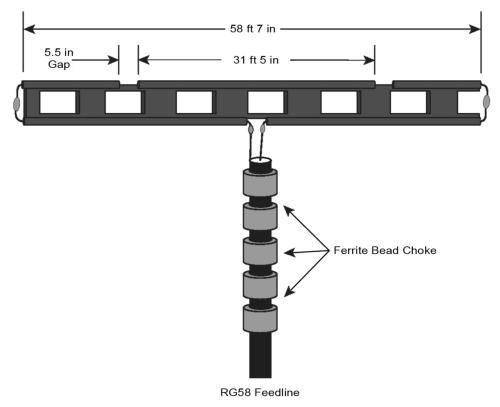
I have taken Figure 1 from the QST article and added my dimensions to it (see above). The wire lengths shown here are
my final lengths. I used the tried and true method of building long and then trimming to resonance. But, building long and
trimming to resonance is a bit tricky with this antenna as there are three different critical dimension that interact with each
other and, thus, three different places you can trim. You can trim from the gap ends of either the 40 meter or 20 meter
sections which, obviously, will end up making the gap bigger. Or, you can trim from the outside ends of the overall length,
where the 40 meter section makes its U-turn, which means you are trimming double the length from the 40 meter section with
each cut you make.
What this comes down to is deciding where you will put the gap in your initial build. I made my initial 20 meter section
31 feet 6 inches long with a 2.5 inch gap, and then made the overall length of the antenna 60 feet long. That overall length
ended up being overkill but I wanted to make sure I had plenty of slack. When I was done, I had trimmed from both the
outside ends of the 40 meter section and the gap ends of the 40 meter section, and very little (about a half inch) off each end
of the gap end of the 20 meter section. YMMV. If you
decide to build this antenna, you may want to have some
extra window line on hand in case you need to start over.
Don’t ask me how I know this.
My window line was Part# 553 from The Wireman and
my coax was Part# 129FF also from The Wireman. This
coax is an RG58 with an aluminum foil shield between the
braid and the dielectric. The foil seems to be strongly glued
to the dielectric which made it very difficult to strip the foil off
of the foam polyethylene. I’m not sure I would use this
cable again for this reason. The ferrite beads were five
FB56-31’s from Palomar Engineers. Palomar also sells
their beads in a single module, snap on or slip on.
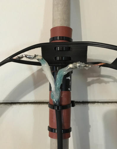
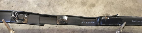
I attached the antenna to the top section of the MFJ
mast (0.75 in O.D.) as follows: The mast was first wrapped
(see left and right) with a rubber gasket material purchased
from the plumbing supply section of a home improvement
store; the rubber was attached with electrical tape to hold it
in place and then further attached to the mast with a couple of plastic zip ties. The was
done to provide a “sticky” or high friction surface on the fiberglass mast. I drilled four
holes in the very center of the antenna window line and these holes were used to
attached the line to the top of the mast, also using a couple of zip ties. The ferrite
beads were threaded onto the coax and covered with a section of shrink tubing; the
coax was then attached to the mast with a single zip tie about an inch below where the
center conductor and the shield separate at the top of the coax. The coax wires were
then soldered, one to each leg of the bottom wire (the 40 meter section) of the window
line. I had teased the copper clad wire of the window line out of the plastic insulation
but left the insulation in place to provide a bit more rigidity to the assembly. I applied
caulk to the open end of the coax; make sure that the exposed braid is either fully
saturated with solder and/or covered with caulk to prevent water infiltration. Once the
caulk had dried I added a second zip tie to the cable and the mast, just below where the
shield and center conductor exit the coax. Finally, the shrink tubing was shrunk and two
additional zip ties were used to further attach the coax to the
mast above and below the torroids. Be careful that you don’t
over tighten the zip ties and deform the coax, possibly
affecting it’s RF properties.
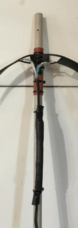
As a final gesture to structural integrity, I reinforced the
gaps. Both gaps ended up spanning multiple windows in the
window line, giving each leg a sloppy feel and allowing for
more rotation in the ends of the antenna than I thought desirable. I used electical tape to
spliced in a couple of sections of blank plastic (the wire had been cut out) from a spare
section of window line.
The resulting assembly would probably not win any prizes for beauty and might not
be what you would want to do if the antenna is going to be exposed to the elements
24/7/365 but, in my case, the antenna will only be exposed for a little over 12 hours and I
felt all of the above was “good enough.”
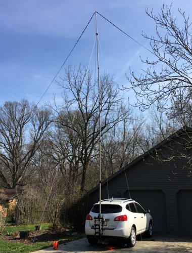
When the mast is raised the feed point of the antenna is at about 30 feet and the
legs of the antenna are at 90 degrees from each other. The mast is guyed five ways:
there are two rope guys to the luggage rack on top of the vehicle with a third rope guy tied
to a concrete block placed on the ground directly behind the vehicle. The two legs of the
antenna then form the final two guys and these are also tied to concrete blocks. The
advantage of the blocks, in conjunction with variable length rope, is that they are easily
moved one way or another, allowing for adjustment based on variability in terrain. They
can also be quickly deployed and then put back into the car when it’s time to move on, no
need to pound anchors into the ground and and then remove. The whole assembly feels
very stable and received its initial testing in ~10 mph sustained winds.
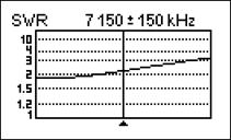
I used a
RigExpert AA230
antenna analyzer
to test for
resonance. Here
are the final
curves for 40M
and 20M. The
internal tuner of
my Icom 756
ProIII had no trouble tuning anywhere within either band.
The antenna was further tested on the air while parked in my driveway during the April 6 1900Z CWOps Mini-
CWT Test. The Mini-
CWT’s are one hour
contests with lots of
domestic activity and
some DX. I made 50
QSO’s, some while
calling CQ but most
while in S&P mode.
The QSO’s were split
almost evenly between
40 and 20; 20 meter
contacts included
QSO’s with France and
Sweden. I felt like we
were in business.
The day of the
INQP dawned gray
and, well, windy. Very
windy. As in 25-MPH-
gusts windy. Our first
stop was at a vacant
industrial building on
the White/Jasper
county line, which is
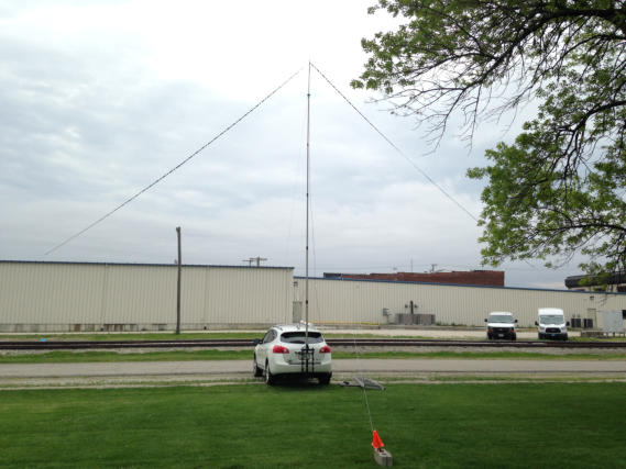
pretty much prairie. We tried to erect the antenna on the
west side of the building and were defeated by the wind. We
then spent several minutes driving around the building, trying
to find a sheltered location and finally ended up nestled
against the east side of the building. It was hard to judge how
the antenna was performing as there was probably some interaction with the building and the wind gusts kept everything in motion. See K9ELF photo at
right. The bend in the mast was from the wind. After about an hour the wind changed directions and started doing scary things to the mast. We finally
dropped the mast out of safety concerns and switched to the Hustlers. Score: Weather 1, Mast 0.
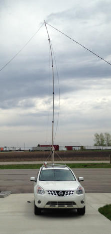
Our second stop was at a park in Goodland, Newton County. See K9ELF photo at left. Not a dense urban environment by any stretch of the
imagination but certainly more wind-sheltered than the first stop and with the antenna largely in the clear. We began to get the sense that the antenna
was a winner, logging 52 phone and CW QSO’s in 42 actual operating minutes. That equates to about a 75-hour rate which, for a state QSO party, is
pretty good. Mind, this was not on a county line so those were all individual, unique QSO’s. This impression held fast at our later stops, and as the day
went on the winds decreased By the time we got to our last stop on the Benton/Tippecanoe line, the wind had died down to very managable levels and
was a non-issue. We also grew adept at the deployment/stowing thing and were able to do one or the other in about 10 minutes.
Bottom line, the antenna worked well for our application, leading to the best-ever INQP for K9WX, based on QSO’s made, points, multipliers and
total score. I would recommend it as long as you don’t have to put it up or take it down in high winds. See our final 2016 INQP stats and additional
comments on my 2016 Contests page.
As always, thanks to Andy K9ELF for a great contest experience.


K9WX Amateur Radio